Payment Type: T/T,Others
Transportation: Ocean,Land,Air,Express,Others
| screen size | |
| Resolution | |
| Contact Now |
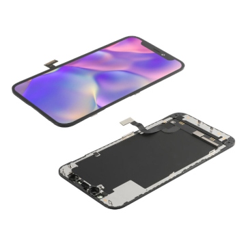
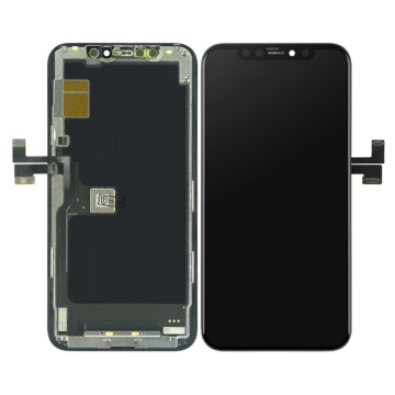
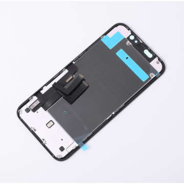
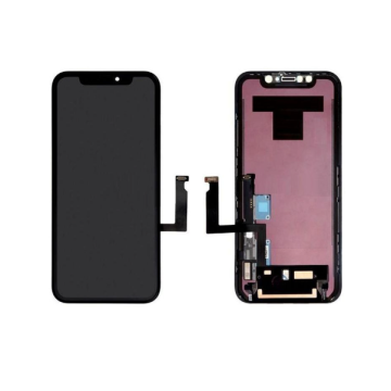
Model No.: LCD Touch screen For iPhone XR Manufacturers
Brand: stars
Warranty Period (years): None
Colour: Black
Is There A Package: Yes
Series: For Business
After-sales Service: Call Center And On-Line Technical Support
Product Status: New
Place Of Origin: China
| Selling Units | : | Piece/Pieces |
|---|---|---|
| Picture Example | : |

|
How to solve the electromagnetic interference problem of the touch screen
Developing mobile handheld devices with touchscreen HMIs is a complex design challenge, especially for projected capacitive touchscreen designs, which represent the current mainstream technology for multi-touch interfaces. The projected capacitive touch screen can accurately locate the position where the finger touches the screen, and it can judge the position of the finger by measuring the small change of capacitance. A key design consideration in such touchscreen applications is the effect of electromagnetic interference (EMI) on system performance. Performance degradation caused by interference can have a detrimental effect on touch screen designs, and these sources of interference will be explored and analyzed in this article.

Projected capacitive touch screen structure
Typical projected capacitive sensors are mounted beneath a glass or plastic cover. Figure 1 shows a simplified side view of a two-layer sensor. The transmit (Tx) and receive (Rx) electrodes are connected to transparent indium tin oxide (ITO), forming a cross matrix, with each Tx-Rx junction having a characteristic capacitance. The Tx ITO is located below the Rx ITO, separated by a polymer film or optical glue (OCA). As shown in the figure, the direction of the Tx electrodes is from left to right, and the direction of the Rx electrodes is from the outside to the inside of the paper.
How the sensor works
Let's analyze the operation of the touch screen without considering the interference factors for a moment: the operator's finger is said to be at ground potential. Rx is held at ground potential by the touch screen controller circuit, while Tx voltage is variable. The varying Tx voltage causes current to flow through the Tx-Rx capacitor. A carefully balanced Rx integrated circuit, isolates and measures the charge entering Rx. The measured charge represents the "mutual capacitance" connecting Tx and Rx.
Sensor status: not touched
Figure 2 shows a schematic diagram of the magnetic force lines in the untouched state. In the absence of finger touch, the Tx-Rx flux lines occupy a considerable amount of space inside the cover. The fringe flux lines are projected out of the electrode structure, hence the term "projected capacitance".
Sensor state: touch
When a finger touches the cover, magnetic force lines are formed between Tx and the finger, and these magnetic force lines replace a large number of Tx-Rx fringing magnetic fields, as shown in Figure 3. In this way, the finger touch reduces the Tx-Rx mutual capacitance. The charge measurement circuit identifies the changing capacitance (△C), thereby detecting a finger over the Tx-Rx junction. By performing △C measurement on all intersections of the Tx-Rx matrix, the touch distribution map of the entire panel can be obtained.
Figure 3 also shows another important effect: the capacitive coupling between the finger and the Rx electrodes. Through this path, electrical interference may couple to Rx. Some degree of finger-Rx coupling is unavoidable.
Productivity: 1000/day
Transportation: Ocean,Land,Air,Express,Others
Place of Origin: china
HS Code: XR LCD
Payment Type: T/T,Others
Incoterm: FOB,EXW
Hot Products
SEND INQUIRY